Winding of middle voltage windings
As the number of turns on the LV side is low, the MV winding will require a significant number of turns so as to maintain the turns ratio. The current is low, so the required cross section of the conductor is small. The conductor for such a winding is most often of a circular or oval cross section with an enamelled surface, thus providing for the insulation between the adjacent turns. A conductor of circular cross-section cannot be wound into a continuous disc winding, so it is most often wound as a layer winding.
The biggest problem in terms of insulation occurs between the beginning of the layer and the end of the next layer, which are the spots with the highest voltage stress. Previously, interlayer insulation of only one width was used along the entire winding height, but today’s technology allows progressive interlayer insulation, where the thinnest insulation can be found between two layers and the thickest insulation is between the beginning and end of these adjacent layers, resulting in reduced overall winding width, so the limb spacing of the core may be smaller. In cross section, the interlayer insulation has a shape of a wedge, see. Fig. 1. Besides, it is necessary to take into account the distribution of impulse voltage among the turns, because due to the inductance and intercoil capacitance the distribution is nonlinear and the turns at the head or tail of the windings are much more stressed than in the middle layers. Therefore, the insulation thickness between the first and last layerss must be greater than within the rest of the winding. In addition, the insulation at the ends of the windings should be wound similarly to LV windings. Today’s technology uses the same insulation strip to create both interlayer and end insulation. Ideally, the selected strip must be of the same width as the end insulation, or narrower.
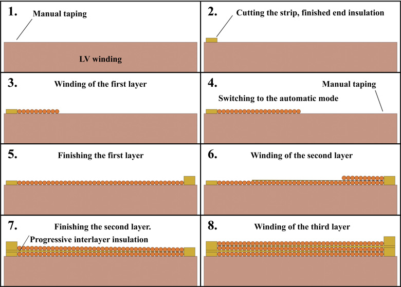
Fig. 1 Progressive winding
Similarly to LV windings, we can form axial cooling channels for MV windings. However, we have to add leadouts of ± 2 · 2,5 %, which is a common practice. The conductor must be split to divide it into two sections, and a bent wire must be led out four times, which slows down the winding process a lot. For these reasons, the MV winding is technologically much more demanding and longer in terms of time.
The above- mentioned company Tuboly-Astronic AG or the German company BR Technologies GmbH & Co. KG are engaged in the production and development of winding machines ensuring the process of winding MV windings. We also use the AM 3150 VPS-3 layer winding machine, which is from the latter manufacturer. Its function and winding procedure will be described further on.
Wire feed
The drum with a conductive wire is placed in a protective barrel. In the upper base of the barrel there is a hole through which the wire is led to the lifting unit. This is represented by a funnel which straightens the wire and leads it to the lifting roll on which there are several loops of wire and these are held by two pressure rollers. From the lifting unit the wire is further led via support rollers between the flattening rollers. The gap between the flattening rollers is adjustable. The wire, after passing through the gap, is flattened and has a smaller thickness, thus improving the filling factor of the MV winding. The result is less material used, smaller windings and as a result, lower costs. The distance between the flattening rollers can be adjusted by means of spindles and possible flattening depends mainly on the hardness of the conductor material and the strength of the enamel on its surface. In the case of an aluminum conductor, flattening can be up to 45 % and if a copper conductor is used, it is up to 30 %. Nevertheless, the wire should be flattened by at least 10 %, as the pressure forms tension necessary for its winding. A dynamic tensioning device also contributes to the creation of tension. It maintains a constant tension of the wire even during winding of non-circular windings at high speed. The tension can be calculated automatically or selected by the operator. In the case of a particularly thin wire, the winding machine is also equipped with a mini compensator of wire tension.
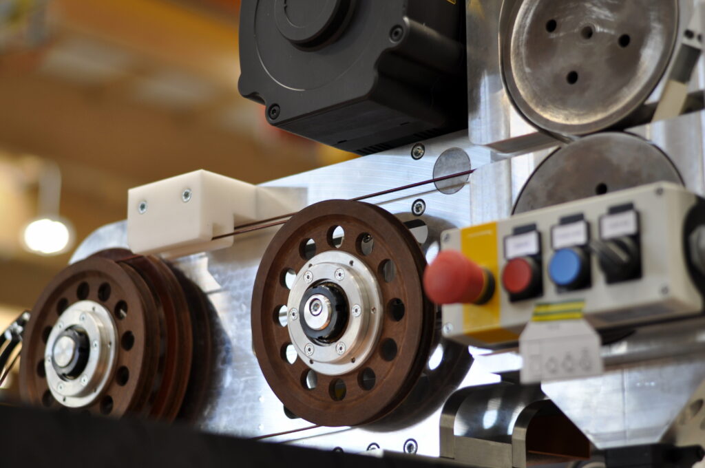
Fig. 2 Wire is fed to the winding
The lifting unit is equipped with a sensor for detecting wire breakage. In case the wire breaks, the machine stops. The end of the broken wire must not pass through the flattening rollers, as the wire would lose tension. Therefore, a new wire must be connected in advance. The scale, on which a protective drum with wire is placed, is also used to detect the wire end. It also reports the weight of the remaining wire at the moment.
Winding unit for insulation strips
The unit for winding insulation strips is designed to wind a progressively shaped interlayer insulation. Depending on the winding design, it is possible to use one or two insulation strips at the same time, and in the case of using two insulation strips, it is possible to add an additional third strip when winding the end insulation. All strips must be of the same width. An offset can be selected between the first and second insulation strips, which makes the wound insulation layer even smoother. The rolls of insulation strip are attached one under the other on the mechanism that feeds the strips to the windings. The mechanisms for the upper and lower strip are separated from each other, and the additional third strip is attached to the upper one. Both structures are actuated in the transverse direction by the actuator so that their position can be changed during the winding along the entire height of the winding.
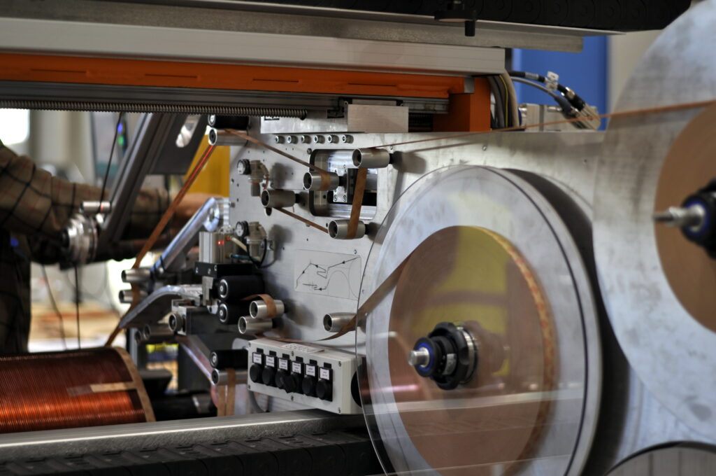
Fig. 3 Feeding of paper interlayer insulation
The insulation is wound along with the conductor, which allows automatic winding. In order to meet the condition for a fully automatic mode, it is necessary for the designed end, and in total also for the interlayer insulation, to be formed by the same number of turns in one layer, just like the wire above this insulation layer. At the design stage, this requirement can be met by a suitable choice of thickness of the insulating strip. If two strips are used, both of them must be of the same thickness to provide for the same tension. All necessary manual operations performed by the machine operator, such as leading out the wire or inserting cooling channels, are also included in the winding process. In such a case, the winding machine automatically stops at all necessary points and alerts the operators.
During the winding process, it is possible to set the parameters of each layer specifically, which makes it possible to wind the insulation in each interlayer with a different thickness, taking into account the voltage stress caused by a pulse wave. The thickness of the insulation strip (when using two or only one of them), is given by the interlayer with the largest thickness, which is most often the first or last interlayer in the winding process. If the design in other interlayer requires a thinner layer of the interlayer insulation, the machine switches to a semi-automatic mode because the operator has to cut the insulation strip at a certain point and stick it again at the next layer, thus reducing the winding speed. Alternatively, the third strip may be used for the interlayer with the thickest insulation. The third strip is automatically inserted between the two main insulation strips when the end insulation is being formed. After the end has been completed, the third strip is automatically cut off. In the other layers, the amount of the third strip is reduced, so the final thickness of the entire interlayer is corrected without the operator´s intervention, which results in increasing the speed and the process flow as well as the cost savings while less glue is used.
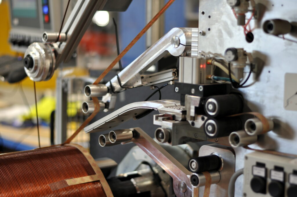
Fig. 4 Winding insulation and wire in detail
The third additional strip can be of any thickness independent of the main strips. The constant tension of the strips is ensured by a dynamic tensioning device, whose position compensates for the non-circular shape of the windings.
Winding mandrel
The expansion mandrel is designed for oval-shaped windings. It consists of a basic body and a casing that is replaceable. The range is manually adjustable. The mandrel is attached to a swing bearing and is supported by a tailstock on the other side. It is very similar to a mandrel for a LV winding machine.
Winding process
The finished LV windings are transferred (usually by crane using fastening straps, small power windings can be transferred manually) to the pivoting mandrel of the MV winder and the mandrel is stretched, thus fixing the winding.
Firstly, only the end insulation without wire is wound. The insulation strips are attached to the edge of the winding with an adhesive tape and a few turns are made until the height of the insulation layer has reached the width of the wire. Then, the insulation strips are cut off and their end is glued. After that, wire continues to be wound without the insulation strips. Now, the beginning of wire is pulled out vertically to the end of the winding in length of about 30 cm as far as the end insulation, thus making a leadout, then it is bent back and fastened behind the end insulation. The leadout part of the wire is tucked into the insulation tube. Subsequently, winding of the first layer starts. The winding machine stops a few turns before the end of the first layer, then the insulation strip is glued again to make an end insulation on the other edge of the winding. At the moment the last turn of the first layer is made, the end insulation is already completed even for the second layer. When the second layer begins to be wound, the insulation strips run under the wire and at the same time a progressive interlayer insulation begins to be wound by gradually thickening the layers of the strips to form the end insulation for the second and third layers on the other edge of the winding. This procedure can be seen in Fig.1. It is, therefore, a fully automatic mode and all other layers are wound in the same way until there is a requirement for a leadout or a cooling channel.
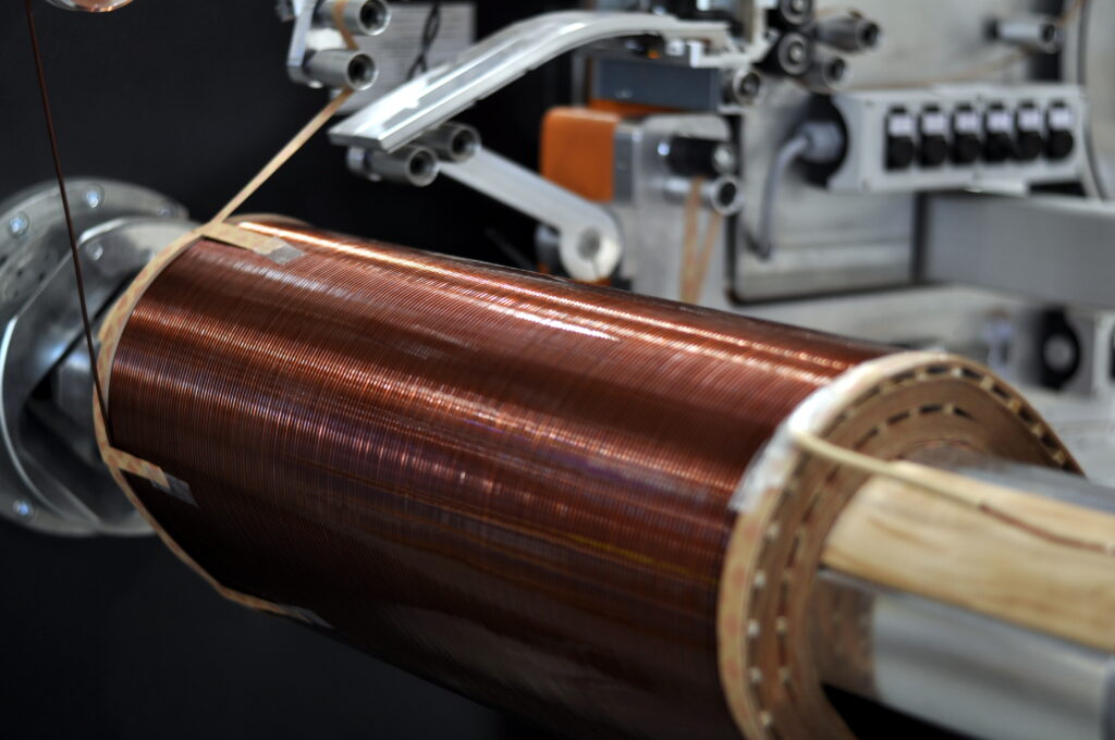
Fig. 5 Winding procedure of MV winding
When the leadouts are to be made, the operator has to pull enough wire from the feeder, approx. 30 cm, and get it outside the winding. Then he bends the wire and returns it to the place where the winding process continues. The leadout wire is inserted into the insulation tube and it is glued where the last turn was made and at the end of the winding. In these places it is also wrapped with additional insulation paper. At the end of the winding, the leadouts are not created around the whole perimeter, but on the opposite side with the LV leadouts and close to each other with a small spacing. Their order is the same as the order of switches in the tap changer. The middle leadouts are formed in the same way, but the wire is split and either of its ends is tucked into a separate insulation tube. The leadouts must be designed so that the turn around which they are made is not very close to the edge, otherwise the leadout cannot be attached well.
When winding the last layer, the end insulation does not have to reach the end of the winding, it can be formed at any height of the winding. As soon as the last loop is made, the wire is led out in the same way as its beginning or the leadouts. In the end, the whole winding is wrapped with a sufficient layer of strips to create a perfect external insulation.
Source: MRAJCA, Miroslav. Design of Oil Distribution Transformer. Brno, 2021. Also available from: https://www.vutbr.cz/en/