COILS - DESIGN
A three-phase double winding transformer is supposed to contain separate primary and secondary windings. Both of them form concentric cylinders along with a core limb which provides a path of low magnetic resistance to close the loop of magnetic flux. Unlike MV winding, LV winding is usually closer to the core as there is no need for such a strong insulation between it and the core. The turns of the conductor are thus wound with a smaller radius while the radius of the insulation for the MV winding increases more than if the windings were reversed. And this is economically advantageous because the costs of insulation are negligible compared to the costs of a conductor.
The overall size of the transformer depends on the size of the coils, as they determine the dimensions of the window, which the core and its shape create. This also affects the cross-sectional size of the core, because the flux density depends on the cross-section and the grade of electrical steel of the core, which determines the no-load losses. A designer must strive for the most compact arrangement of the coils, i.e.to be solid and use the space as efficiently as possible. In contrast, there is need to provide some space for cooling channels, insulation, gaps between the core and the coils and among the coils themselves for the passage of oil. Most importantly, the designer must make an effort to obtain the largest possible cross-section of the conductor, which was mostly made of copper in the past, today made of aluminum, in order to minimize short-circuit losses.
The following section describes how the best compromise is reached between these conflicting goals in practice. First of all, it is necessary to deal with the topic of short-circuit losses in more detail. Short-circuit losses of the transformer are defined as losses caused by the passage of a load current and they vary with the square of the load current. As for the transformers, we can distinguish three types of short-circuit losses
- Ohmic losses, often referred to as I2R.
- Eddy current losses in the winding caused by alternating leakage fluxes passing through the winding. The result of these eddy currents is a skin effect and a proximity effect.
- The so-called additional losses in the leadouts, the tightened structure of the core and the tank caused by leakage magnetic flux.
Of course, losses occurred directly in the winding play the largest part. Ohmic losses, as the term suggests, are caused by the fact that the winding cannot be manufactured without the presence of electrical resistance. However, there are ways how to reduce losses as much as possible:
- Using material with the lowest resistivity, which is, of course, copper with high conductivity. However, currently, from an economic point of view, mainly aluminum is used.
- Using as few turns as possible.
- Increasing the cross-section of the conductor in the coil.
Minimizing the number of turns in the winding process means that the core must operate with the highest possible flux density and must have an adequately large cross-section. However, increasing the size and weight of the core means that no-load losses increase counterproductively. Reducing short-circuit losses thus comes at the expense of increasing no-load losses and vice versa. Increasing the cross section of the core results in the increase of leakage reactance, so the axial length of the winding must be shortened to compensate for this change. It is therefore up to the designer to find a reasonable optimum between these conflicting requirements.
The disadvantage of increasing the cross-section of the conductor is enlargement of the window, which results in a higher leakage flux. The voltage induced in the conductor leeds to the formation of eddy currents. In addition, the larger the cross-section of the conductor, the lower the resistance to induced voltage by leakage flux, and thus the magnitude of the eddy currents increases. The only way to increase the eddy current resistivity is to divide the conductor into several subconductors that are insulated from each other. However, the use of more bundled conductors pays off only for larger outputs, not for distribution transformers. Since eddy currents are the result of leakage magnetic flux, flux reduction also leads to the reduction in eddy currents. For example, a high thin core will be characterized by less flux scattering and also less eddy currents than a core that is low and thick.
Winding of low voltage coils
Low voltage coils, more precisely coils with a maximum operating voltage of up to 1.1 kV, i.e. more than 90% of distribution transformers, are almost always made in the form of foil winding. The coil can be simply imagined as a roll of aluminium foil or a coil capacitor. This technology is effective because although only about 30 turns are needed on the LV side, large electric current flows through the coil (e.g. rated current of 909 A flows through a 630 kVA transformer). In order to ensure an acceptable current density (max. 1,5 A/mm2 for aluminium and for copper 2 A/mm2), it is necessary to achieve a large conductor cross-section, therefore the width of the foil occupies the entire height of the winding. The advantages of this method are high speed and simplicity of winding, significantly reduced additional losses, high short-circuit strength due to current distribution along the entire length of the coil, axial cooling channels can be easily introduced without reducing mechanical strength and balanced temperature distribution in the coils.

Fig. 1 Foil winding machine
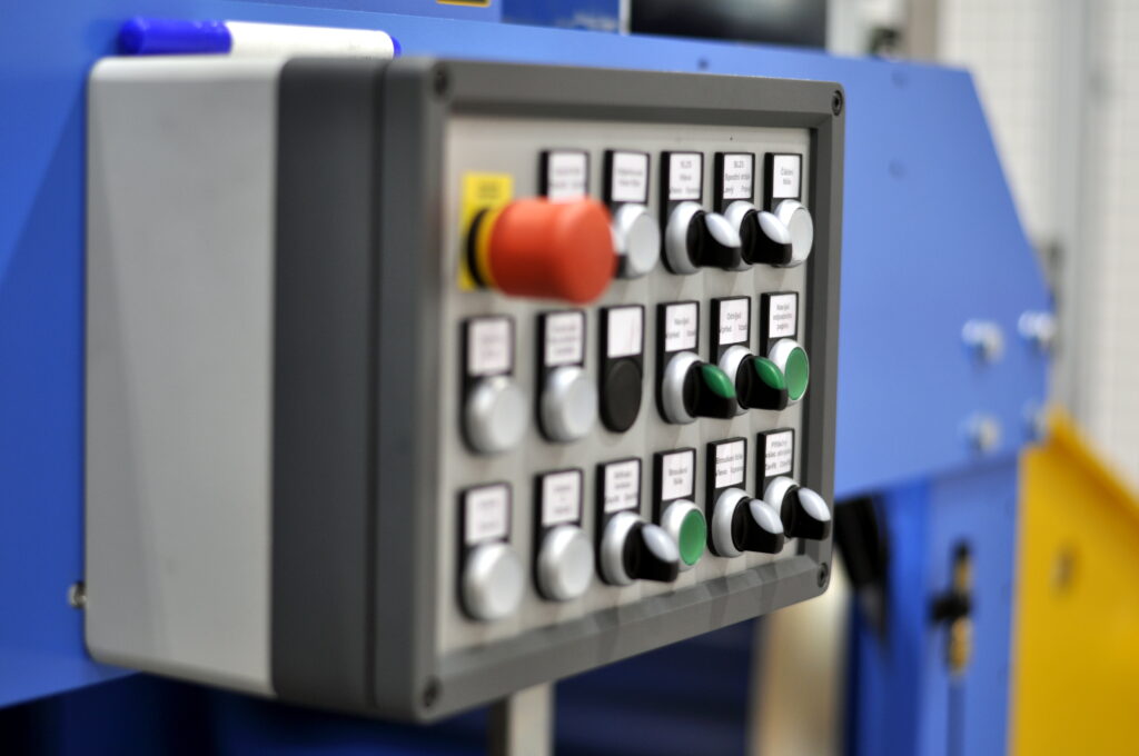
Fig. 2 Control panel
Special winding machines are used to wind a foil. The most famous manufacturer of these winding machines in Europe is the Swiss company Tuboly-Astronic AG. The most suitable model for distribution transformers made by this manufacturer is the EFECO 800-1 C foil winding machine, which is again used also by Elpro-Energo s.r.o. A description of the function of such a machine and the manufacturing process are stated in the following paragraphs. The EFECO 800-1 C has a modular construction. It consists of a foil decoiler, foil treatment units, an insulation decoiler and a place where the coils are wound.
Conductor foil decoiler
The winding machine is equipped with one decoiler of a conductor foil, see Fig 1. The casing for the conductor foil decoiler is mounted on a transversely sliding unit. The accuracy of the position of the foil edges is monitored and regulated by a photocell attached to the casing of the winding machine. In case of any deviation, the uncoiler moves to the correct position. This control feature guarantees a highly accurate position of the foil edges, which does not depend on the winding speed. This system allows the coils to be wound within a narrow tolerance range.
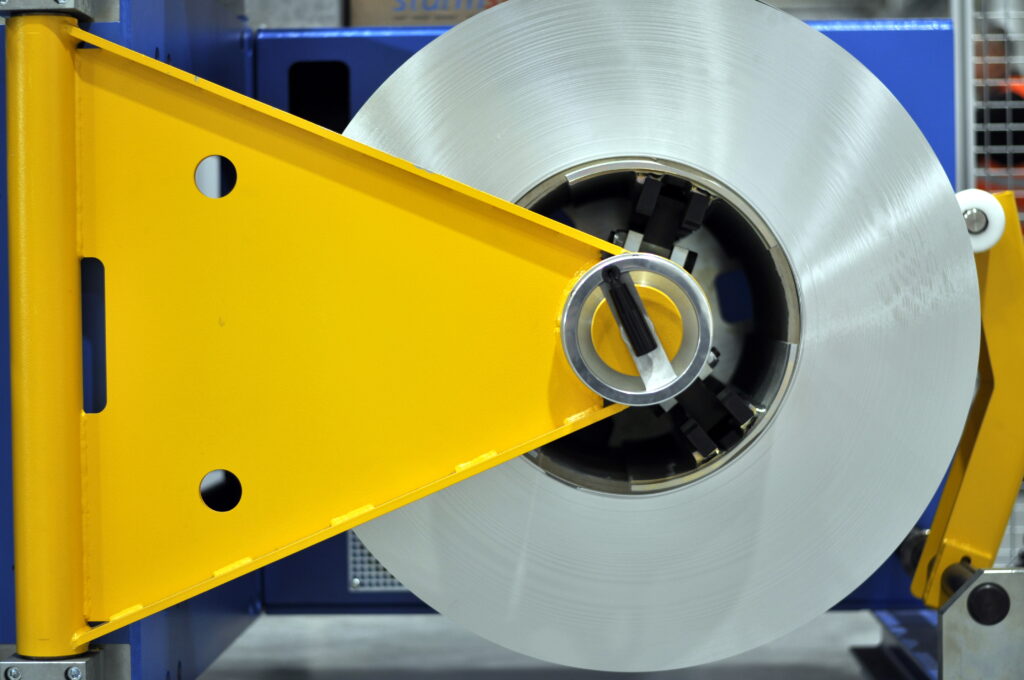
Fig. 3 Conductor foil decoiler
Attached to the casing, a manually-operated expanding mandrel enables inserting the coil. The mechanical expansion system allows quick and easy loading on the decoiler. In order to be able to stretch the foil without any displacement to the side, the surface of the jaws is fully serrated. The decoiler can be loaded by means of a crane, then the mandrel is supported by a counter swing bearing.
The decoiler mandrel can be braked by a pneumatically operated disc brake unit. The tension of the foil is continuously adjustable with respect to the foil cross section. The automatic system compensating the winding diameter maintains a constant foil tension within the entire diameter range. The decoiler is equipped with a pressure roller which remains pressed against the roll during the winding process, thus preventing it from coming loose.
Foil treatment units
Leaving the decoiler, the foil first proceeds to the unit treating its edges. Two pneumatically operated rollers are pressed on both edges, aligning all protruding burrs. Next, the foil is prepared for cold pressure welding which must create a perfect mechanical and electrical connection with a leadout. This requires a grinding unit removing oxidized layers. The grinding unit is followed by a welding station. The cold pressure unit enables joining aluminum with aluminum, aluminum with copper and copper with copper. The welding unit and the principle of its function are shown in Fig. 4. The welding unit consists of a robust steel frame built into the middle part of the winding machine. The transverse movement and the pressing process take place automatically. Prior to welding, the foils and the leadouts are clamped by means of holders located on the left and right edges of the foil and the surfaces which are to be pressed are coated with a paste preventing the foil from sticking to the press. The leadouts are made of a strip of rectangular cross-section, mostly of the same material as the conductor. They are connected to the conductor over the entire width of the conductor and the protruding part of the leadout is bent twice to keep it within a sufficient distance from the core. Holes are usually drilled at the end of the leadout for easy connection of continuing conductors.
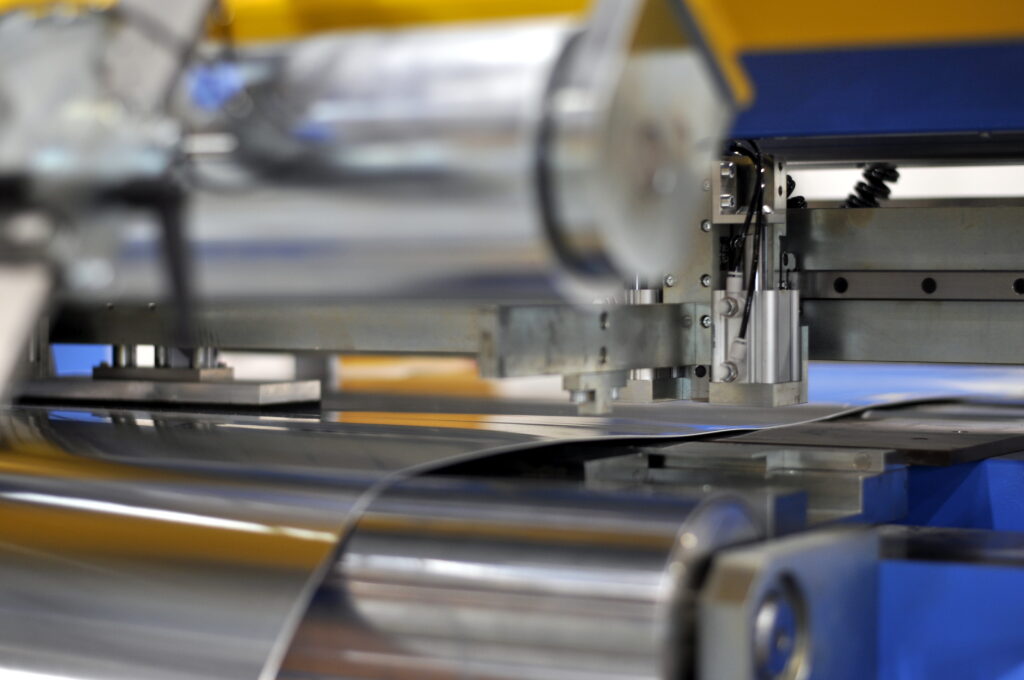
Fig. 4 Cold pressure welding
After trimming the edges, the position of the foil is monitored by a photocell and, in the event of a shift, the decoiler is instructed to make alignment. Behind the welding unit there is also a measuring cylinder, which is equipped with a encoder, by means of which preliminary stop points are calculated, e.g. for pressing the leadouts or inserting axial cooling channels. Above the measuring roller there is a roller for counter-bending the foil.
The advantage of counter-bending of the foil is that the foil fits much better around the corners of the oval or square coils. A few turns before the coil is completed, the counter-bending roller moves away from the foil to avoid incorrect calculation of stop points. Both rollers can be seen in Fig. 5.
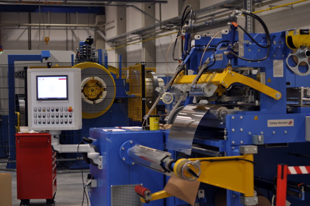
Fig. 5 Counter bending roller and measuring roller
Insulation decoiler
Below the foil treatment unit there is an expansion mandrel for loading a roll of insulation paper. There is a scale allowing precise adjustment of edges, here you can also set a knife which cuts the paper edges while being unwound to achieve the desired width, as the rolls are produced only in standardized widths, see Fig. 6. The advantage is a significant reduction in stored widths of insulation papers. The paper is tensioned by a pneumatic disc brake, which is regulated by a sensor measuring the diameter of the roll. The machine can be equipped with more insulation decoilers.
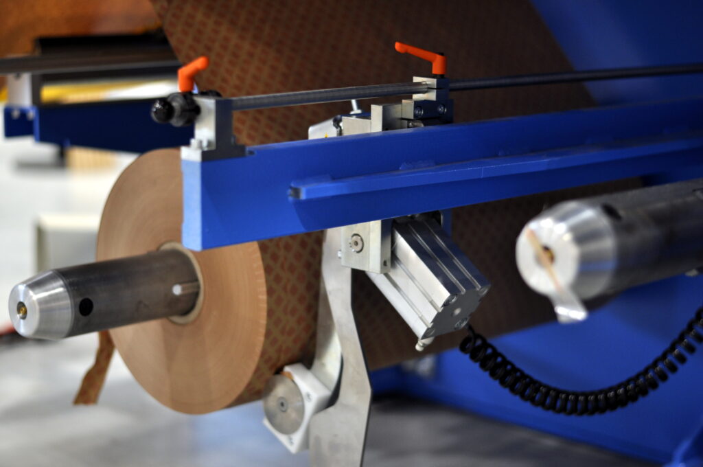
Fig. 6 Insulation paper decoiler
The other two decoilers, this time for the edge insulation tape, are located above the foil treatment unit. Both systems can be manually moved sideways for precise adjustment of the foil edges. The tapes are fed to the decoiler by tilting arms.
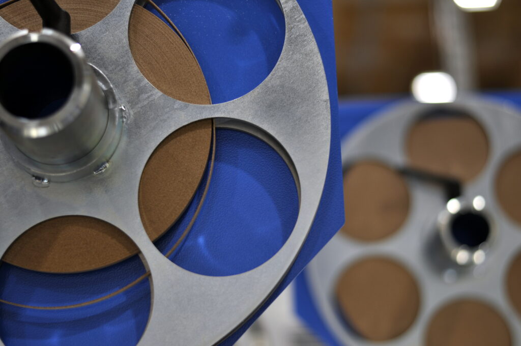
Fig. 7 Decoilers of edge insulation tape
Winder of winding
The winding machine is designed in a similar way as the foil decoiler which is located on the opposite side of the machine. The casing of the winding machine is made of a solid steel construction. The winding shaft is mounted in robust bearings. The flange welded to the winding shaft carries the winding mandrel. To ensure maximum tension, the shaft is equipped with a swing counter bearing. The shape of the coils is maintained by a pressure roller.
The mandrel consists of two half-cylindrical panels, in one of which there is a groove for the leadout at the beginning of the coil. The length of the straight part is increased by putting spacers under these panels. The straight part consists of two side panels whose distance from the flange can be again adjusted by spacers.
Winding process
From the decoiler, the foil is stretched into the foil treatment unit. Its beginning part is sanded, covered with a paste and it is welded to the leadout by cold press. The foil is further stretched as far as the winding mandrel and the leadout is inserted into the groove which holds the foil and ensures the required tension. Subsequently, it is turned a little and the insulation paper is pulled out of the lower part of the winding system and tucked under the foil so that it is firmly gripped by the pressure between the foil and the mandrel. Afterwards, edge insulation tapes are pulled out of the upper part of the winder. They will fill the gaps on the edges between the protruding main insulation, because they are wider than the conductive foil and overlap both edges. By filling these gaps, the coils are completely insulated. At the beginning of the winding process, the edge insulation tapes must be attached to the foil with an adhesive tape.
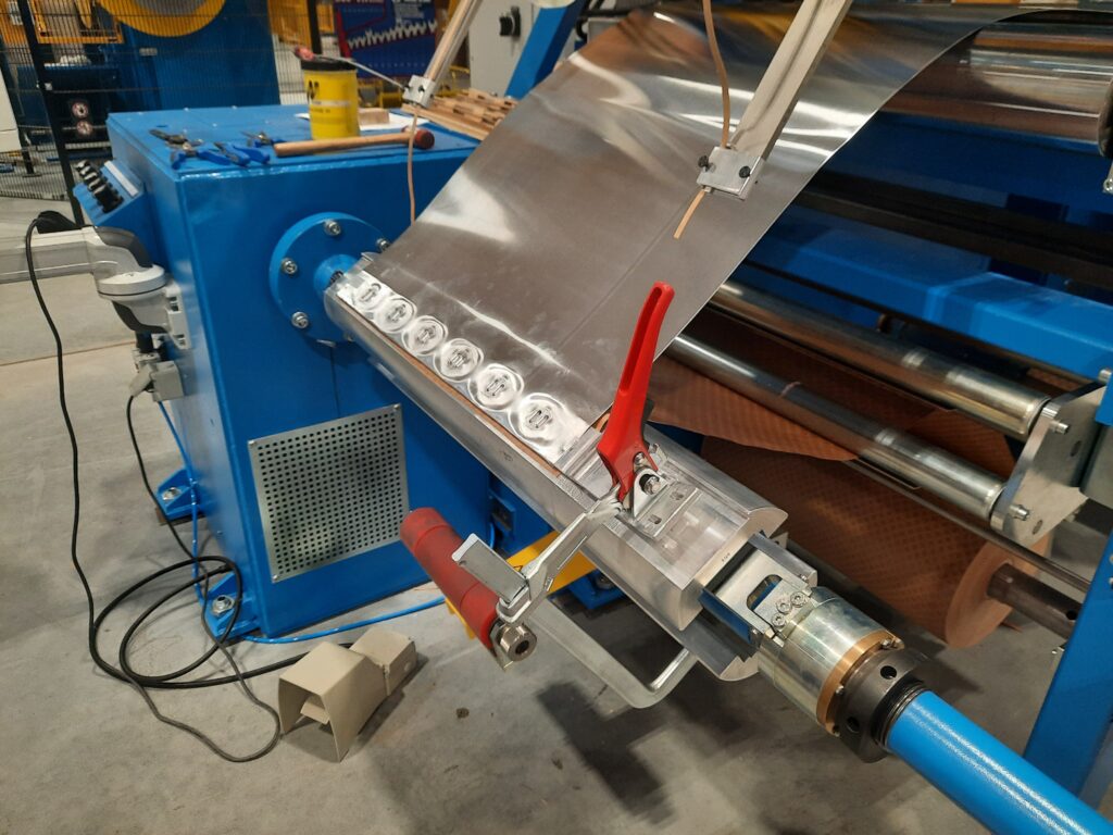
Fig. 8 Beginning of winding process
The continuous rotation of the winding mandrel then goes on until a required number of turns has been achieved or until an axial cooling channel needs to be created in the coil (for higher transformer powers). In such a case, the process is stopped and the operator must insert a taped mat between the first and last wound layer, and he will create a gap between these turns. The mat is rewound in a slow and controlled manner through a new turn, then it is possible to continue the winding process at a standard speed.
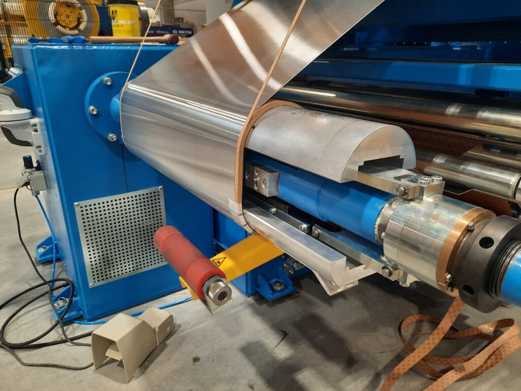
Fig. 9. Winding process
Just before the completion of the last turn, the winding process is stopped and again, the leadout is welded to the foil in a precisely calculated point so that it is located exactly above the first leadout on the coil. After welding the end leadout, another leadout can be welded as well because it will form the beginning of a new coil. The foil between these two leadouts is cut by electric scissors, which are a part of the winding machine. When the required number of turns is met, the insulation strips on edge are cut to correspond to the end of the conductive foil. Here it is taped again to the winding. Then, a 1 mm thick insulation cardboard, which is slightly wider than the leadout and extends beyond the coil, is added to the outer leadout. Its presence increases the electric strength between the LV leadout and the MV coil because especially the edges of the leadout are very prone to breakdown. The whole coil is then rewound with several turns of the main insulation paper to ensure sufficient electrical strength between the LV and MV coils. Like the cooling channel inside the coil, the main cooling channel, through which oil flows, is inserted in the middle of the insulation between MV and LV. It doesn´t only cool both coils, like the channels in each coil, but also insulates them electrically. After the insulation has made the last turn, the paper is cut off and its end is taped to the coil with an adhesive tape, which is enough for the time being, as now it is time for the MV coils to be wound.
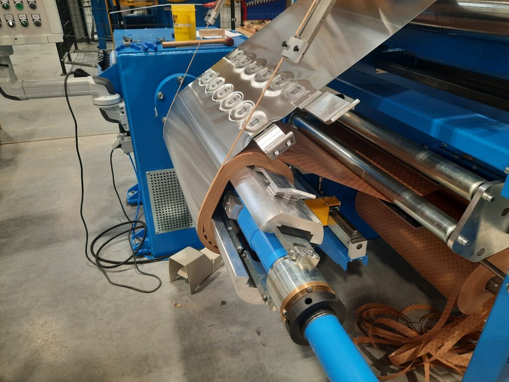
Fig. 10 The end of one coil is the beginning of the other one
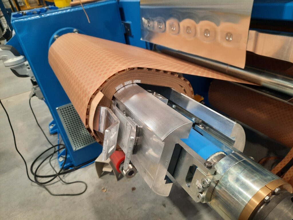
Fig. 11 Finished LV coil
Source: MRAJCA, Miroslav. Design of Oil Distribution Transformer. Brno, 2021. Also available from: https://www.vutbr.cz/en/