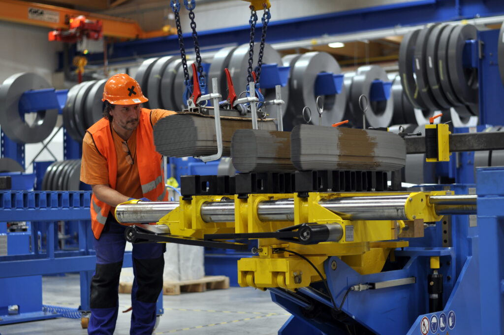
Building a magnetic circuit can be done in two different ways – in a vertical or horizontal position. The horizontal method requires a specially adjustable industrial tilt table, but the vertical one requires even its rotation by 180° in addition. In the vertical position, however, stacking laminations is easier and also less time-consuming. In both processes, the magnetic circuit is built without an upper yoke, the magnetic circuit is then E-shaped. The upper yoke is inserted only after all coils have been put onto the limbs.
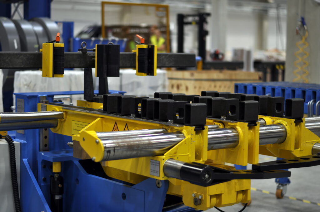
Fig. 1 3t assembly table by Georg
The whole process of building starts already on the stacker, where laminations are already grouped into limbs and yokes. The alignment pins are replaced by others, more suitable for the transfer of whole limbs which have a fixed shape. The limbs are removed by crane.
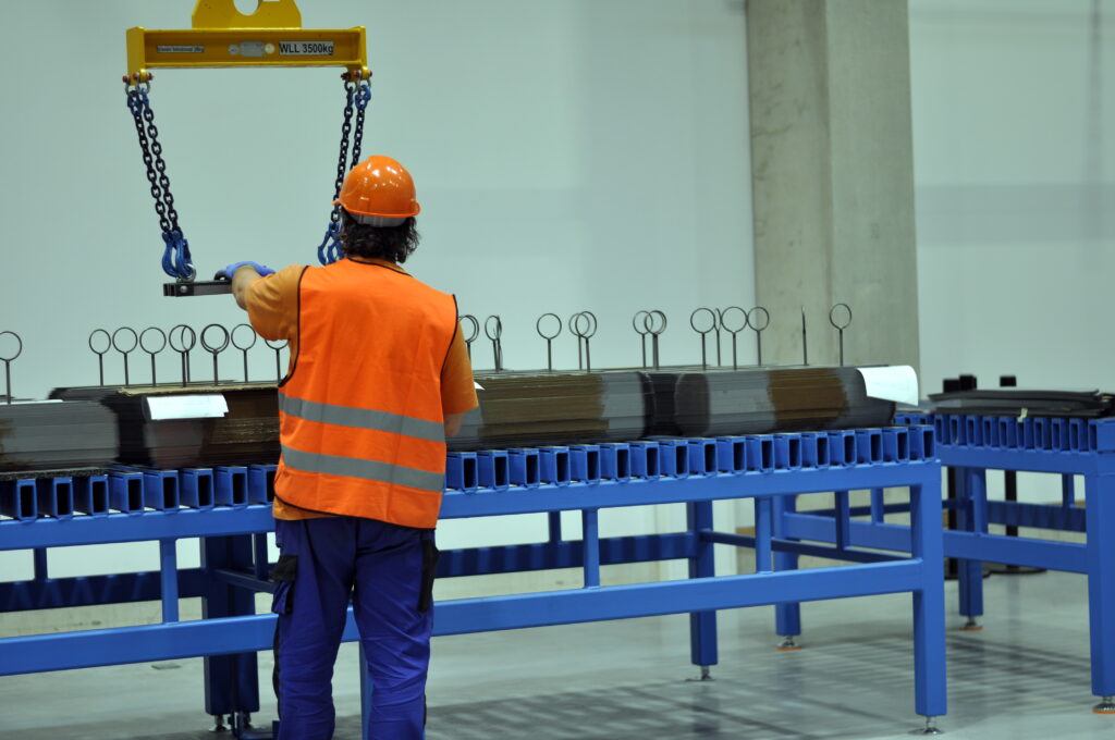
Fig. 2 Ready-cut limbs are moved to assembly table
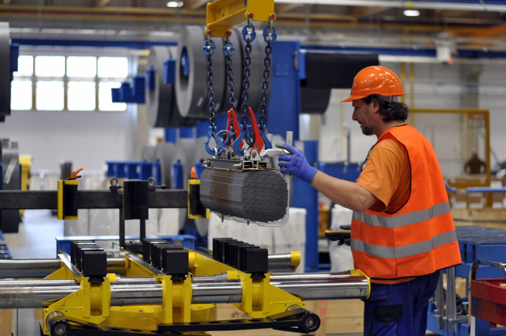
Obr. 3 Fixing limbs on assembly table
All limbs are then fixed with aligning pins to the assemble table. It consists of holders for limbs, where the position of the middle holder is fixed and the side ones have an adjustable distance from the middle holder by means of spindle drives, so as to correspond with the design of the core. Stands for aligning pins and small supports are then placed on the holders. Being in a certain distance from each other, they support the limbs as well as small supports for the yokes. After putting the limbs on the table, iron plates with holes are placed on their top under the pins. After that lever clamps are used to fix the iron plates so that the limbs remain in a completely steady position and no rotation, however small, is possible as every millimeter can affect the result of the assembly process. The limbs are further reinforced by a traverse on the side where the yoke is placed after the coils have been put on. The traverse has polyethylene jaws into which the ends of the limbs are inserted. The traverse is attached to the holders and is pressed to the legs.
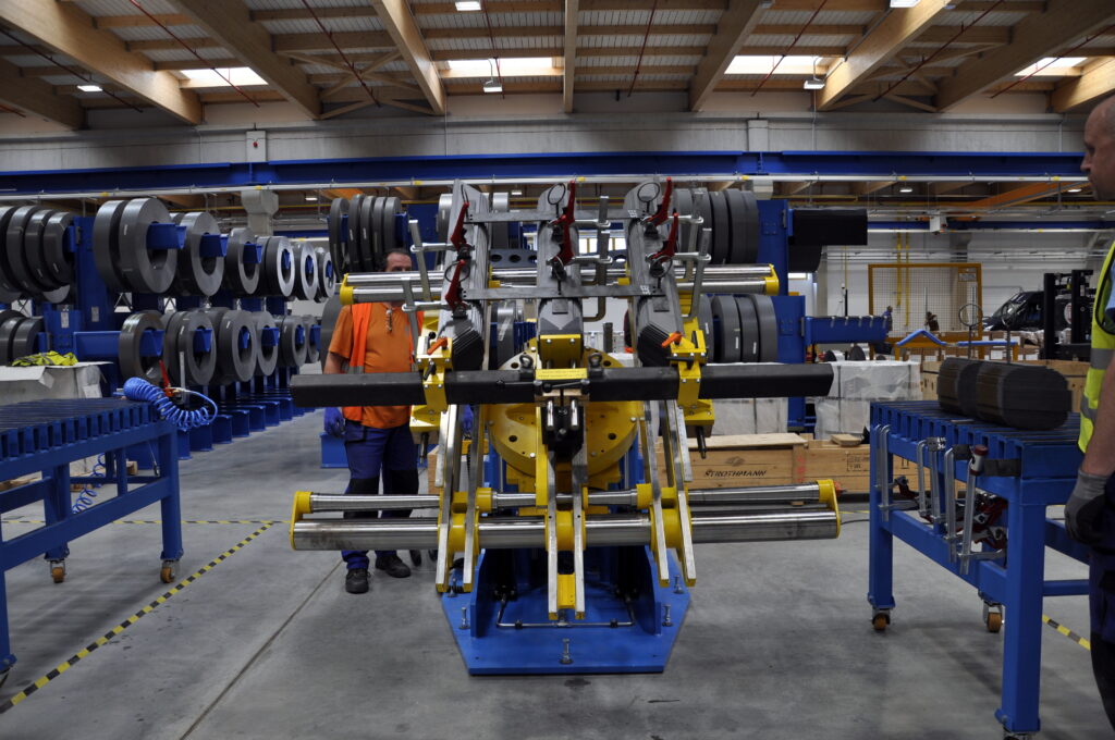
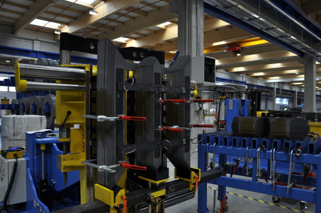
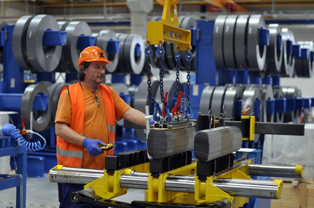
Fig. 4 Tilting core to vertical position
For vertical building, the table is tilted by 90° towards the ground by means of traverse and the lower yoke, now appearing as an upper yoke, begins to be built by individual packets. Workers must first make room at the ends of the limbs with a spatula so that correct connection of individual laminations in each joint can be clearly seen. Starting with the lowest packet, which is the narrowest, the access is quite difficult. In order to improve accessibility of these packets at least a little, the cutting process of the core starts on the side where the laminationss have been removed due to the outlets of the LV coils and the limbs are placed on the table on this side. Another help is to center the last few steps of the core which no longer form a flat surface on the coil side, so the laminations are higher and better accessible. This will also cause better distribution of force when tightening the yoke with a tightening construction. In order to make the visibility better it is advisable to cut out limbs with a visible step when stacking laminations in the joint. After the yoke has been finished, the tightening construction, lined with a cardboard, is screwed on. Wooden beams are laid on the top of the limb, and all are tightened with iron tape. The beams are made of wood, because they are not electrically or magnetically conductive and do not increase losses, on the contrary, they absorb oil and perform an insulating function. Then, the yoke is pressed to the legs by screwable tilting supports, which are mounted on the side holders. The table is then returned to the horizontal position and then rotated by 180 ° so that it can be tilted along with the finished yoke towards the ground, and the core can be removed by a crane with straps.
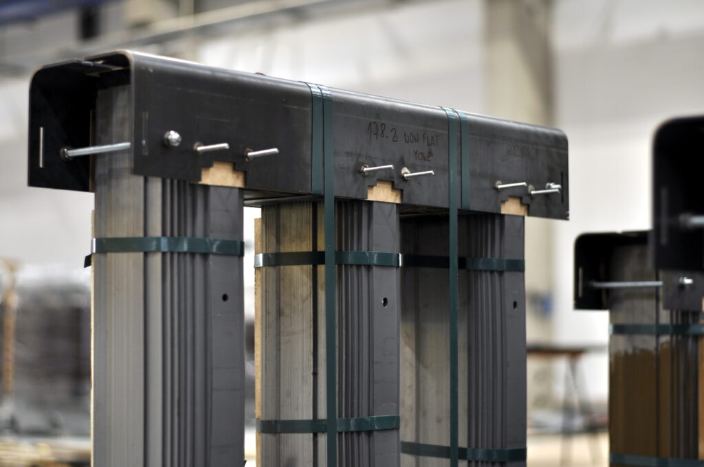
Fig. 5 Finished core ready for inserting coils
As for the horizontal assembly, the lower yoke is built in the same way as in the vertical assembly only in the horizontal position, because the table tilts straight down with the finished yoke.
Source: MRAJCA, Miroslav. Design of Oil Distribution Transformer. Brno, 2021. Also available from: https://www.vutbr.cz/en/studenti/zav-prace/detail/131597. Semestral thesis. Brno University of Technology, Faculty of Electrical Engineering and Communication Technologies, Department of Power Electrical Engineering and Electronics. Thesis supervisor Čestmír Ondrůšek.