The following description relates to a large-scale automatic cutting line made by the largest cutting line manufacturer – the German company Georg GmbH. The Georg precisioncut TBA 400 model made by this manufacturer is also used by Elpro-Energo s.r.o. The function of the line can be divided into three parts.
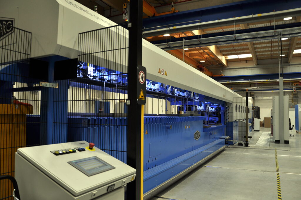
Fig. 1 Georg precisioncut TBA 400
Unwinding machine
The first part consists of four unwinding mandrels, on which coils of electrical steel of a required width are inserted. As it is shown in Fig. 2, the unwinding mandrels are attached to a rotatable cross head. When cutting, it is possible to switch quickly to another coil by turning to the next mandrel. Since the core usually has more than four steps, it is necessary to cut laminations of more than four widths of one electrical steel strip, so the coils need to be changed continually. The great advantage of having more mandrels is the possibility of changing a coil by the operator, while another coil on the opposite mandrel is being unwound and cut at the same time. So as to maximally save time, it is important to replace the coils during the cutting process efficiently, as it is the careful removal of the coil from the mandrel and its placement on a prepared spot (e.g. a coil stand) and then subsequent insertion of a new coil that takes up the most time during the cutting process. Each mandrel has four segments which are hydraulically expandable to be able to grip the center of the coil firmly.
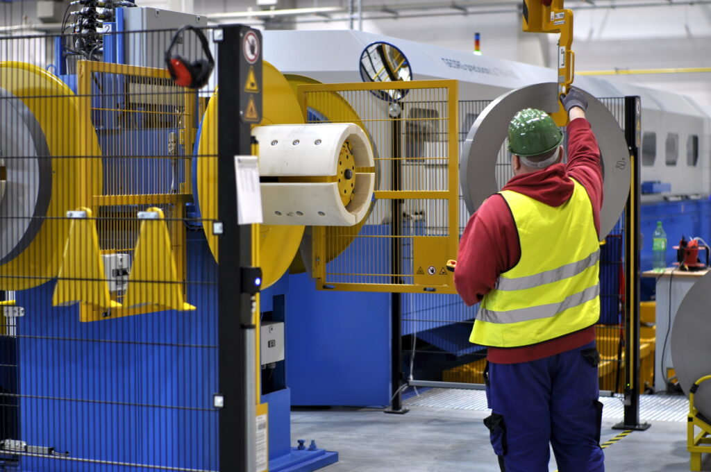
Fig. 2 Unwinding device with 4 mandrels
At the beginning of cutting one thickness, the operator unwinds the end of the coil by manually controlling the rotation of the mandrel with the coil. He then inserts its end into the next part of the cutting line, which controls the movement of the electrical steel strip automatically. Likewise, at the end of cutting process and changing the coil, the operator must first cut off the rest of the strip, then pull it out and manually rewind it back on the coil. It is sufficient to use a strip of adhesive tape to fix the coil so that it does not unwind. The rest of the electrical steel strip which has been cut off is put in waste.
Cutting part of the line
In the next part of the cutting line, the electrical steel strip enters the feeder formed by two rollers, which control the movement of the electrical steel strip. The lower roller is driven by a servomotor and the pressure of the upper one is adjustable. The individual layers of the core are then cut out of the electrical steel strip. The laminations are cut out exactly as following: a yoke, a side limb, a yoke, a side limb and a central limb. The whole sequence keeps repeating as it is shown in Fig. 3.
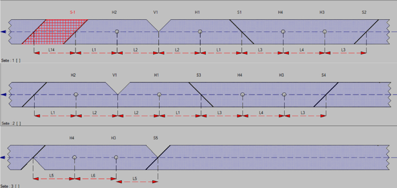
Fig. 3 A sequence of cutting a electrical steel strip
The electrical steel strip passes through two pairs of hole punch pliers, each pair punches holes in one piece with a diameter of 10 mm for alignment in the stack. All hole punch pliers are movable in the longitudinal direction, they are controlled by a servomotor. Between the second pair of pliers there is a tool for cutting a V-notch. This notch is formed in the middle of the yoke for connection with the middle limb. The tool for cutting out the V-notch is movable in a transverse direction with the strip so that it can change its position to create a step-lap overlap. At the very end of the sequence, the V-notch is also applied on the middle limb to achieve the desired shape of its end. The individual laminations are then separated from each other by two shears, which form 45° with the edge of the sheet and 90° with each other. The layout of the tools in the line is shown in Fig. 4.
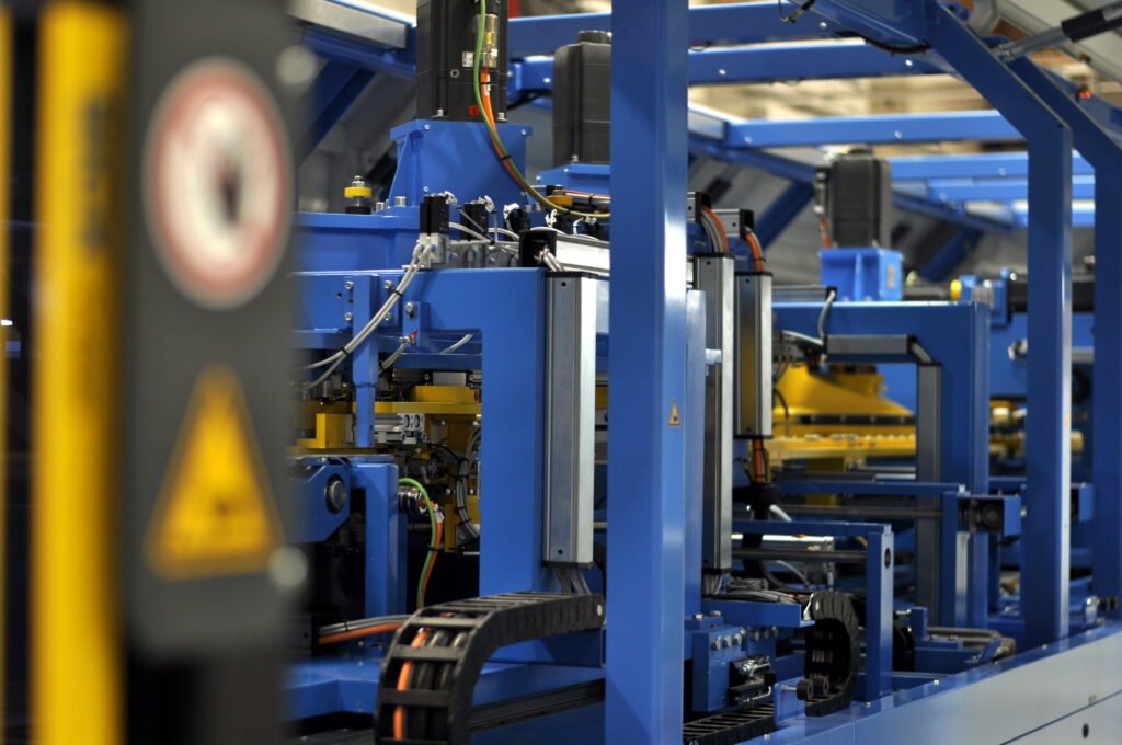
Fig. 4 Detail of the layout of the tools in the line
The first shears are movable only in a transverse direction, the second ones also in a longitudinal direction. Needing just one stop, they manage to cut off one yoke and one side limb at the same time. The same idea is applied for double hole punch pliers, where aligning holes and a V-notch are punched into the same parts at the same time. This greatly speeds up the process, as doubling saves two belt stops. The last part in a sequence, the middle limb, passes through the perforation and the (V-notch at the end of the sheet for separation. The desired shape of both connecting edges is then achieved with shears. Between the sequences, when the whole layer is being cut, one piece of lamination is cut and put into waste (red hatched part in Fig. 3), because the V-notch and the subsequent cut at an angle of 45° do not always fit together precisely, and a tooth or burr may be left on the next yoke, impairing the continuity of the joints and consequently, the properties of the whole core. The scraps of the sheet metal which have been cut and unused are transported to the end of the cutting line, where they end up in a steel recycling container.
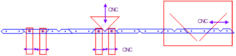
Fig. 5 Diagram of the location of cutting tools in the line
The principle of a step-lap cut is based on the fact that while the edge of the joint moves away from the center of the side limb with each additional layer by the value of the overlap length, in the same sequence the edge of the yoke joint approaches its center, or vice versa. As a result, only the position of the cut between the alignment holes of the side limb and the yoke changes.
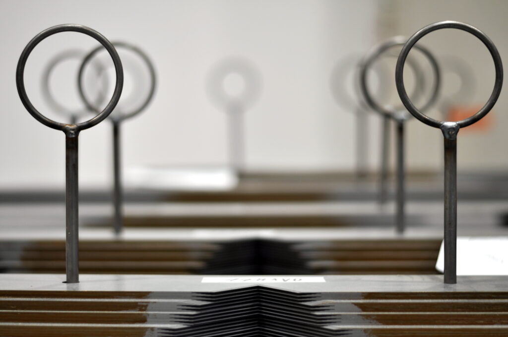
Fig. 6 Example of the V-notch
The cutting points are chosen so that the mean value of the cut between the layers of one packet symmetrically divides the corner of magnetic circuit. When such a symmetry is applied, after assembling a core, the teeth are of the same size and stick out from the side walls of the magnetic circuit as shown in Fig. 7b.
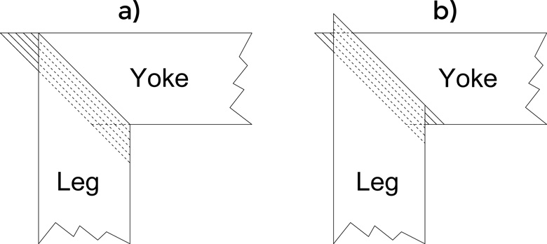
Fig. 7 The difference between the corner joint of two packets a) The widest step b) The other steps
The widest step of the core presents an exception, where the upper and lower area of its magnetic circuit is required to be straight, without teeth caused by the step-lap. All teeth protrude from the side of the left and right limb at the widest step as shown in Fig. 7a. Such an alternative allows the clamping structure to hold the yoke as tightly as possible.
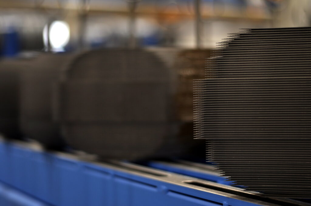
Fig. 8 Detail of step- lap joint
Four procedures are used to cut lamination so that the step-lap joints fit properly. To distinguish them, it is necessary to define a visible and invisible step. The visible step means that at the edge of the packet of the limb or yoke there is a lamination with the largest overlap in the lower layer of the packet and the smallest overlap in the upper layer of the packet. In other words, all steps in the packet are visible from the top. If we turn over the packet, we get an invisible step. In order to assemble the core correctly, the joint of the limb is created using an invisible step and a visible step is used for the joint of the yoke, or vice versa. The step-lap cutting configurations are as follows:
- a) Vertical plane-symmetrical step-lap – Both joints of all limbs are equally visible or invisible steps, yoke joints are then all with the opposite steps (see Fig. 9a).
- Vertical axially symmetrical step-lap – The yoke has a uniform step in all of its joints, but both yokes have opposite steps. The layers of the limbs are then of the same length, only the position of the alignment holes is different (see Fig. 9b).
- Hybrid step-lap – It is identical with the horizontal step-lap except for the solution of joints for the middle limb which is identical with the vertical solution (see Fig. 9c).
- Horizontal step-lap – Both end joints of each part have opposite steps and the middle limb consists of a half-invisible step and a half- visible step. The overlap of the sheets does not move in a vertical direction, like the points a, b, c, but in a horizontal direction (hence the name of the division).The sheets of all layers of the side limbs and both yokes have the same dimensions, only the holes are shifted (see Fig. 9d).
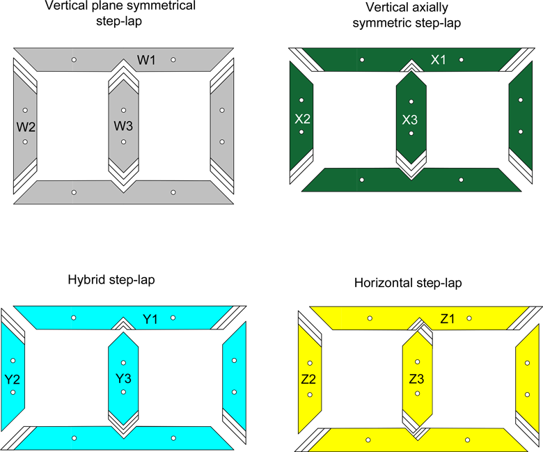
Fig. 9 Types of step- lap
Stacker
A belt conveyor transports cut laminations over the stacker. The upper surface of the stacker consists of welded rectangular steel tubes, which are arranged in parallel, transversely to the direction of laminations movement. The pitch of the pipes is 100 mm and the same pitch in the transverse direction is applied for the holes for alignment pins (therefore the distance between the holes in lamination must be an integer multiple of 100 mm). The pins must be manually mounted in the points according to the dimension requirements in the relevant design for cut laminations.
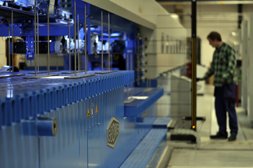
Fig. 10 Stacker
The laminations are transported above these positions by five magnetic servo belt conveyors on the underside of the belt. Such a conveyor can be seen in Fig. 11. Once a pre-set stacking position is reached by the control system, a magnetic bar moves away from the belt and the lamination is dropped right through the punched holes for the pins, sliding down in perfect alignment with the rest of the stack. The stack gradually grows until it forms a complete limb or yoke. For this reason, the process begins with cutting the narrowest coil of lamination and follows to the widest one and back again by the individual widths of the core steps, as demonstrated in Fig. 11. In order to make cutting procedure as time-efficient as possible, particularly replacements of lamination coils, it is advisable to cut several pieces of magnetic circuit at the same time, ideally of the same or more designs and the same widths of electrical steel strips.
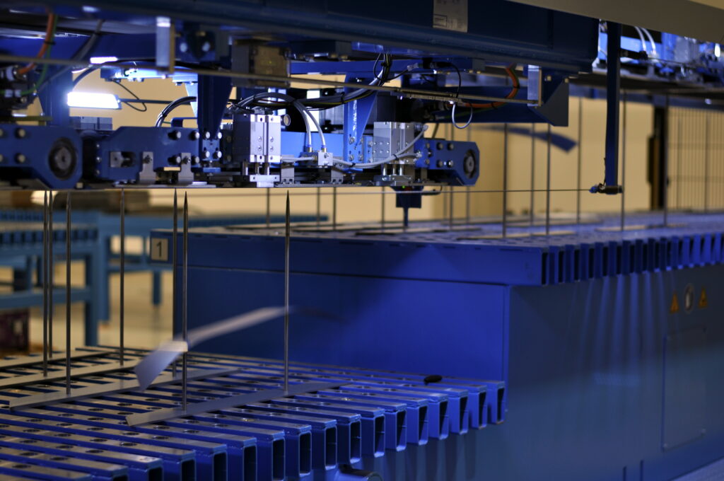
Fig. 11 Dropping of lamination
For this reason, a stacker is wide enough to provide enough space for more pieces in the transverse direction. The stacker moves on linear bearings located on the base beams. Its movement is motorized, which allows batch production with automatic movement of the stacker and a pneumatic centering device, thus achieving precise positioning for different transverse stacking positions (see Fig. 12). The position of the stacker does not change until the full height of a given step thickness is achieved in the whole row (for a complete one / two cores). In order to achieve a maximum cutting performance and minimize the movement of the stacker, it is best if a full sequence (one magnetic circuit) fits in one row on the stacker.
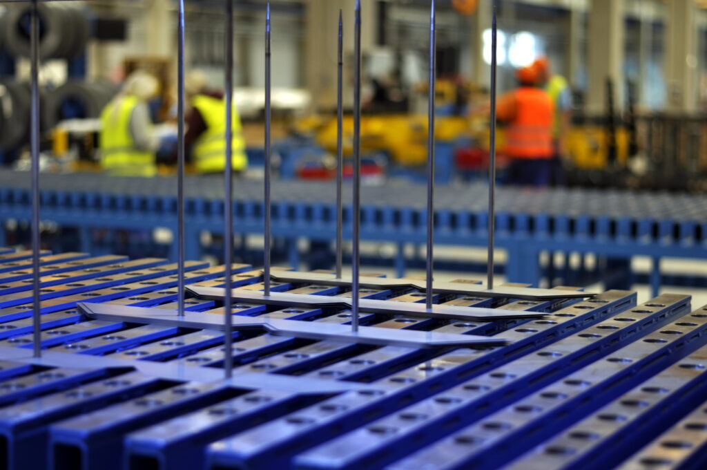
Fig. 12 Placement of laminations on stacker
For medium lengths of laminations of less than 650 mm, 10 stacking spaces can be created in one row, so two full cutting sequences (two identical magnetic circuits) can fit there, which results in even higher performance. As to the laminations of medium length up to 1200 mm, 5 stacking spaces can fit in one row. Laminations of medium length up to 2200 mm or 2500 mm have 3 or 2 stacking spaces available, which already requires a different cutting sequence. However, the sheets of such lengths are required only for transformers with the power of 10 or 20 MVA.
The Georg precisioncut TBA 400 even uses two stackers, both of which can be swapped automatically. On one of them, stacking procedure can take place, while from the other, ready cut cores are being taken away, or positions of the alignment pins are being changed for the following designs.
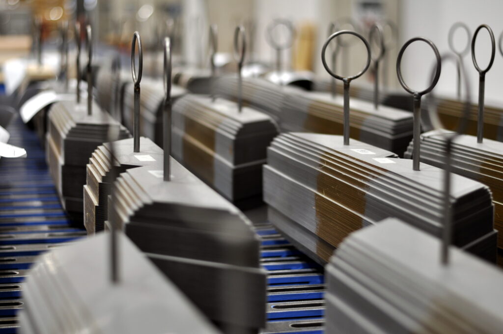
Fig. 13 Yokes and limbs ready for assembly
Laser measurement of packet height plays an important part in the stacking process. It is needed to compensate for the actual sheet thickness, as there are some deviations from the theoretical value.
The height is measured automatically on one limb or yoke and the height of the remaining stacks is corrected accordingly. The compensation involves measuring the height of the entire stack and based on it, the current height of step is calculated. This is divided by the number of laminations in it and the average actual thickness of used coil is specified then. Subsequently, it is calculated how many more layers (usually the actual lamination is thinner) are needed to be cut, in contrast to the calculated number of sheets, to maintain the required step height. To speed up the process, only the first half of stack is measured, because the second one is cut from the same coils and, from experience, the thickness of the laminations does not change much.
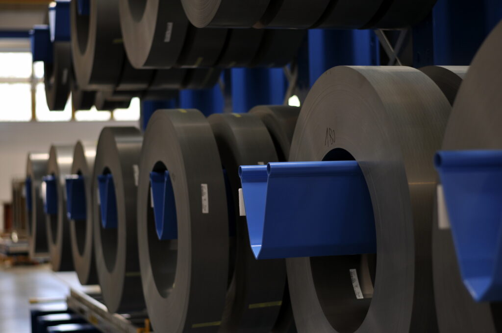
Fig. 14 Stock of electrical steel sheet coils for George
Source: MRAJCA, Miroslav. Design of Oil Distribution Transformer. Brno, 2021. Also available from: https://www.vutbr.cz/en/