

Every transformer, whether cast resin or oil-filled, works with magnetism. Every change in the electric field around a conductor induces a change in the magnetic field, and vice versa. Today, magnetic steel sheets are most commonly used to guide the magnetic flux, internally linking the individual coils together. The system thus created is subject to mutual interaction. The magnetic circuit is called the core and represents the heart of the transformer.
Thanks to the research and development of steel and transformer manufacturers, materials with improved properties have been developed alongside better processing technologies. In the past, sheets used for manufacturing had far inferior properties and, compared to today’s standards, were associated with high losses and magnetizing power. Later, it was discovered that adding silicon (4–5%) to the steel alloy significantly improved the material’s characteristics due to increased electrical resistance and permeability.
Hysteresis losses were also reduced due to the decrease in the area of the B-H loop. Since then, silicon steels have been used in most transformers. Furthermore, the addition of silicon aids in slower aging; although silicon makes the material more brittle, it is not to such an extent that it causes problems during sheet stacking.
Subsequently, cold-rolling sheet technology was introduced, where the grains of the material are oriented in the rolling direction. Processing is carried out such that optimal properties are developed in the rolling direction due to strict control of the orientation of magnetic domains relative to the sheet (developed by Norman P. Goss). In this direction, it has better properties, such as reduced iron losses and low magnetostriction. In the rolling direction, magnetic induction increased by 30%, although magnetic saturation decreased by 5%. Therefore, grain-oriented steel is primarily suitable for transformers, not for the magnetic circuits of motors.
Materials of various qualities were historically introduced in the following order: non-oriented, hot-rolled grain-oriented sheets (HRGO), cold-rolled grain-oriented sheets (CRGO), high-permeability cold-rolled grain-oriented sheets (Hi-B), and mechanically or laser-cut sheets. Today, Hi-B sheets are the most commonly used; compared to CRGO, production is simplified by eliminating one rolling stage due to the addition of approximately 0.025% aluminum to the melt. Hi-B sheets have specific losses 15–20% lower than standard CRGO. Losses can be further reduced by 5–8% through laser treatment, where the magnetic domains are more finely divided.
To reduce eddy current losses, thin sheets are used. Currently, the thickness for power transformers ranges from 0.23 mm to 0.35 mm, while for small transformers, a thickness of up to 0.50 mm is used. It must be taken into account that the smaller the thickness, the longer the core stacking time, because the number of sheets required to achieve the desired cross-section increases. These sheets can operate with a magnetic induction of up to 1.75 T. The introduction of EcoDesign automatically limits the use of transformer sheet quality to a minimum of M085-23, with a specific loss of 0.85 W/kg at an induction of 1.7 T, in this example with a thickness of 0.23 mm.
The sheets are covered with an inorganic insulating layer, typically gray in color, called Carlite. This is the final surface treatment of the transformer sheet. It is a 2–4 µm thick layer formed on both sides of the sheet, protecting against additional eddy currents. It consists of two layers: a base C2 layer (glass film), which forms as a chemical reaction of the surface during high-temperature annealing with MgO, transforming into Mg2SiO4. After final cleaning by another annealing process (800–850 °C), a final C5 phosphate layer is applied. The insulation is sufficient to withstand induced voltages of several volts.
Since the core is in close proximity to the high-voltage winding, it is grounded; otherwise, it could acquire a high potential due to capacitively transferred voltage from the winding. If the core is divided by cooling channels (about 5 mm thick), the individual sections must be grounded. Given that the capacitance between any two adjacent sheets is very high due to their large surface area and the very small insulating gap between them, the capacitive reactance between them is negligible. Therefore, all sheets in one section remain at almost the same potential. Consequently, each of the sections is grounded at only one point.
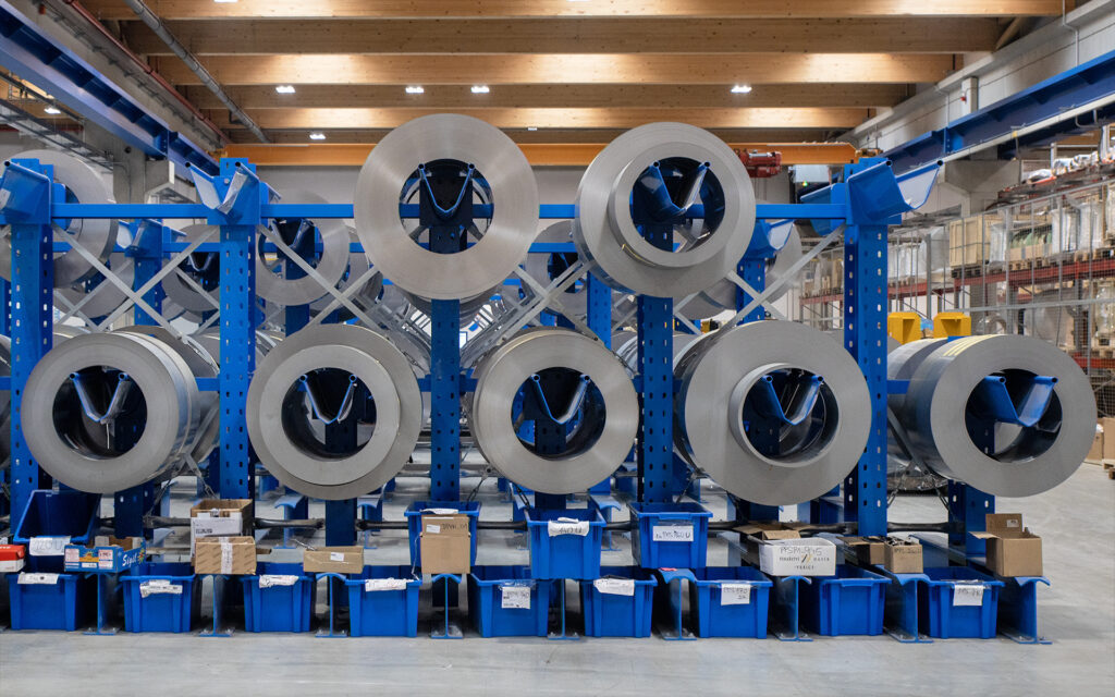
Structural design of the magnetic circuit
For oil-immersed distribution transformers, a three-phase core-type magnetic circuit arrangement is used almost exclusively, see Fig. 1. From an economic standpoint and due to larger dimensions, the shell type (Fig. 1b) is not cost-effective at all, with the possible exception of furnace transformers.
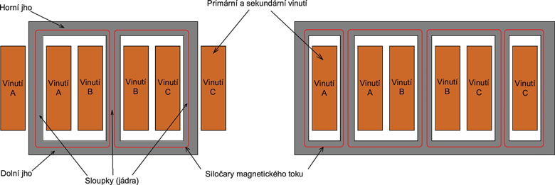
Fig. 1 a) Core-type arrangement of a three-phase transformer b) Shell-type arrangement of a three-phase transformer
The magnetic flux of each phase closes through the limb and returns through the yokes and the remaining two limbs. The cross-section of the limb and the yoke is usually the same; it is also simpler during core punching because one continuous layer is punched from the same coil of sheet metal. Theoretically, lower no-load losses could be achieved by increasing the cross-section of the yoke, but due to the unequal cross-sections, the losses might increase again due to inferior joints between the limbs and yokes, making the reduction of losses ineffective. The core-type construction of a three-phase transformer has its own inherent three-phase asymmetry caused by the unevenly distributed no-load current among the phases. The currents in phases A:B:C are in an approximate ratio of 1 : 0.718 : 1, where B is the middle limb. This inequality is caused by a longer magnetic path for the outer limbs when looking at the length of the magnetic circuit from the perspective of each phase individually. A symmetrical core could be achieved by joining the limbs into a three-dimensional star or triangle, such that the windings would mechanically enclose a 120° angle with each other, but from a manufacturing perspective, such a design is unnecessarily complex.
In large power, cast resin, and older oil-immersed distribution transformers, the core sheets are stacked to create a cross-section as circular as possible to achieve maximum utilization of space inside the cylindrical windings. The stepped cross-section approaches a circular shape only depending on how many different sheet widths the manufacturer has ready for punching. In distribution transformers, the number of steps ranges from just 5 up to 10 or more. The core shape then utilizes approximately 88% and 95% of the circle’s area, respectively. In reality, the area utilization may be slightly lower because manufacturers aim to standardize the range of sheet widths to cover all different core sizes, or they might purchase pre-cut material. In such a case, the standard range of widths provided by the electrical steel manufacturer will be limited, typically graded in 10 mm increments, e.g., from 50 mm to 440 mm in width (due to limitations of the punching machine). Under such conditions, it is unlikely that optimal widths will be available for filling the core for every radius at a given number of steps.
Naturally, the maximum utilization of space is offered by a square or rectangular shape of both the core and the winding simultaneously, where additionally only one sheet width is needed. However, the forces between the windings caused by the short-circuit current, which act on such a shape in critical areas, are too large. The commonly used technology is not sufficient to reinforce the winding to prevent undesired deformation. A comparison of the effects of short-circuit forces between the windings can be seen in Fig. 2.
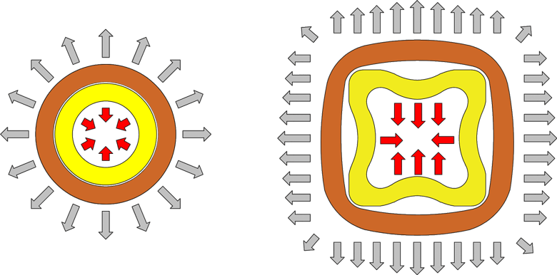
Fig. 2 Effects of short-circuit forces on circular and rectangular winding shapes
In recent years, however, the trend has been to use cores and windings with an oval cross-section. In such a design, the classic circular core is divided into two halves, and an additional step is added between them, representing a straight section (a visual demonstration is in Fig. 3). We well remember the time when the price of copper rose significantly, and manufacturing windings from aluminum became more cost-effective. However, to maintain the same losses, transformers grew in both weight and dimensions, which conflicted with the maximum technical specifications of utility companies. The oval design required innovative and more complex winding technology, such as an oval expanding mandrel, movable rollers in the winding machine to ensure firmness, and dynamic regulation of wire tension to ensure maximum winding speed while maintaining the required precision of winding parameters. It was also necessary to conduct new type tests, which the new design successfully passed. Since short-circuit forces act more destructively in an oval design than in a circular one, in order for the windings—fixed by cured resin-impregnated insulation—to mechanically withstand them with a safety margin, it is recommended that the thickness of the straight section does not exceed 100 mm. The oval core and winding are shown in the middle of Fig. 3.
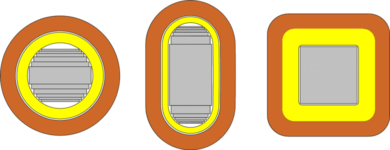
Fig. 3 Cross-section of the core and windings of various shapes; from left: circular, oval, and square.
Regarding the cross-sectional shape of the yoke in oil-immersed distribution transformers, unlike the limb, the trend is no longer to achieve a symmetrical shape (for example, in cast resin transformers, the yoke also has the same oval cross-section as the limb). Instead, there is an effort to rearrange the sheets of the same width as those in the limb so that they form a flat edge on the side facing the windings. This reduces the weight of the magnetic circuit and slightly lowers the losses. Only the last one or two steps are centered widthwise with the preceding step, solely for easier insertion and pressing of the yoke sheets, see Fig. 4.
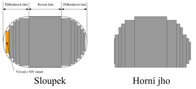
Fig. 4 Comparison of sheet stacking in the cross-section of the limb and the yoke
The ratio between the losses of an assembled magnetic circuit and the mass of the magnetic circuit multiplied by the specific losses is known as the building factor (or no-load destruction factor). The value of this factor is crucial for the correct calculation of the no-load losses of any power or distribution transformer. It is an empirically derived factor based on the experience of the transformer manufacturer, ranging from 1.08 to 1.35 for three-phase core-type magnetic circuits. The building factor is a dimensionless quantity and depends on many variables, such as the quality of the sheet material, the human factor during sheet stacking, and above all, the geometry of the magnetic circuit, i.e., the ratio of the volume of the corner joints to the total volume of the magnetic circuit. Therefore, for small power transformers (25 kVA to 100 kVA), the factor ranges up to 1.25 to 1.35, while for transformers above 25 MVA, the factor will be relatively lower, from 1.08 to 1.15. The value of the building factor thus decreases as the power rating increases, because a higher power rating has a significantly larger ratio between the volume of the core and the volume in the joints; also, any holes are relatively smaller. Since the joint between the limb and yoke sheets primarily determines the magnitude of the building factor, we can categorize these joints in the following chapter.
Classification of cores based on sheet stacking
A non-mitred joint with a 90° edge angle is simpler from a manufacturing perspective, but due to higher losses in the joints, it is used only for small transformers. However, together with non-oriented sheets, they were also used in large power transformers.
With grain-oriented sheets, to limit to some extent the deviation of the magnetic flux from the sheet’s orientation direction in the joints between the limbs and yokes, it is better to cut at a 45° angle, which is the most widely used variant. The mitre angle, however, can also range from 30° to 60°.
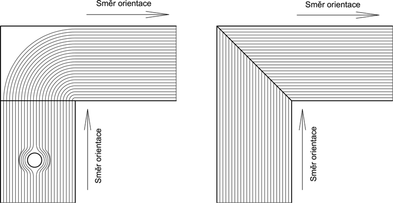
Fig. 5 a) Right-angle edge joint, including the effect of sheet holes on the magnetic flux b) Joint with an edge cut at a 45° angle
Butt joint, non-step-lap, step-lap
The butt joint method consists of stacking the sheets on top of each other so that all layers are identical and the edges in the joint form a continuous surface, see Fig. 5 in the middle. However, this method is unusable in modern large magnetic circuits because the magnetic flux has no other path than through the air gap created in the joint, resulting in significant losses.
These losses can be eliminated by the lapping method, which can be divided into non-step-lap and step-lap. In the construction of a lapped core, the sheets are stacked so that the gaps in the joints between the limbs and yokes are covered by the sheets of the next layer. By staggering the sheets in steps and stacking them on top of each other, the gaps in the joints do not form a flat surface. The size of the overlap ranges from about 15 to 20 mm. In the joints, the magnetic flux can thus continue to the adjacent sheet without passing through the air gap that is directly in its path. The gap in the joints plays a major role in the magnitude of losses and no-load current. Compared to a zero gap, the increase in losses is 1 to 2% for a 1.5 mm gap, 3 to 4% for a 2.0 mm gap, and 8 to 12% for a 3 mm gap. These numbers emphasize how important it is to minimize gaps during sheet stacking.
The step-lap method is characterized by a stepped overlap of the sheets in the joint, where the stepping is achieved by different sheet lengths in each step. The number of steps is usually between 5 and 8, and each step has one or more identical sheets on top of each other. These steps are stacked together so that the joint in cross-section resembles stairs. The sheets that make up one cycle of steps on one piece (yoke or limb) are called a packet (a joint of two packets can be seen on the right in Fig. 6), and these are repeated to achieve the desired step thickness. The step width of a circular core is ideally designed to contain an integer number of packets, or at least so that the last packet is more than half full, for the sake of core stacking efficiency.
Non-step-lap is actually the predecessor of step-lap and is the simplest form of lapping, as it has only two steps, meaning the sheets have only two configurations (see Fig. 6 on the left). However, multiple steps compared to a simple overlap ensure a smoother transition of the magnetic flux through the joint, thereby reducing losses within it. Therefore, non-step-lap is not used in Europe or anywhere else where there are strict requirements for low losses. Distribution transformers with a non-step-lap core are manufactured in India, for example.
Based on experience, it has been shown that the fewer sheets one lapping step contains, the lower the losses generated. For example, a design using two sheets per step has 3 to 4% lower losses compared to four sheets per step, and losses are a further 2 to 3% lower for a single sheet. On the other hand, as the number of sheets per step decreases, the core stacking time increases. In practice, therefore, the use of two sheets per step has proven successful; for example, the company Elpro-Energo s.r.o. uses a 6-step step-lap with 2 sheets per step. The overlap between steps is 3.6 mm, making the full packet overlap 18 mm (with the exception of the 50 mm wide sheet, where for technological reasons, the maximum possible overlap is 2.8 mm per step).
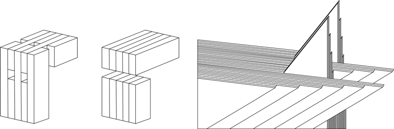
Fig. 6. Detail of the joints; from left: non-step-lap, butt joint, and step-lap (with five steps)
Advantages of step-lap over non-step-lap
When the magnetic flux in the core approaches the air gap in the corner joint with the yoke, it has two options – either it passes through the air gap in the joint, where the permeability is much lower (=1), meaning the magnetic permeance of the air is much lower. The second option for the flux is to cross the insulation between the sheets and transfer into the adjacent sheet in the vertical direction (the direction perpendicular to the rolling direction of the sheets) above or below, where the permeability is on the order of 10⁴, and thus the magnetic reluctance is much lower.
The flux unequivocally chooses the second option, i.e., it passes through the insulation into the sheet above or below it. However, when the CRGO is saturated at a magnetic induction of approximately 2 T, this is a limit state that also allows the flux to cross the air gap in the joint. Consider a core operating at a magnetic induction amplitude of 1.7 T. As the magnetic flux approaches the gap in the joint, it must choose between options 1 and 2 mentioned above.
If all the flux transfers to the adjacent sheet above or below, in a core stacked using the non-step-lap method (where there are only two sheet configurations), the magnetic induction in the overlapping sheet will be 3 · 1.7 / 2 = 2.65 T (see Fig. 7a), which causes a concentration of flux and greatly exceeds the saturation limit of the CRGO sheet (which is approximately 2 T). Consequently, in a non-step-lap joint, a portion of the magnetic flux transfers to the adjacent overlapping sheets, but a portion of the flux will also have to jump across the air gap (which is option 1). Even the flux that transfers to the adjoining sheets increases the magnetic induction within them above the saturation level, which also contributes to the saturation of the material in the joints and thereby increases the no-load losses.
The flux that crosses the air gap contributes to a drop in magnetic potential (magnetomotive force), and covering these losses requires a higher no-load current to achieve the desired magnetic induction in the core. Excessive saturation of the material in the corner joints further leads to higher magnetostriction of the core, which is the main cause of transformer noise.
However, with the step-lap method, the situation is different. The flux approaching the air gap has many more options for transfer, as can be seen in Fig. 7b, simply because there are more layers (steps) of sheets into which the flux can be redistributed. As can be seen in the schematic representation of a six-step core, the flux proportionally has six options for crossing instead of just two, and therefore there is a much more even distribution of flux in the joints, resulting in much less flux jumping directly across the air gap. Thus, the contribution of losses in the corner joints is smaller, and the magnetic induction there remains around the saturation limit, i.e., 2 T.
The transition from non-step-lap to step-lap reduced the building factor by 5 to 8%; in addition to the losses, the no-load current and the transformer noise level also decreased significantly. However, step-lap manufacturing requires a highly precise automatic core cutting line, which represents a major investment.
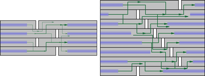
Fig. 7 Magnetic flux path in the joint for a) non-step-lap and b) step-lap
Source: MRAJCA, Miroslav. Design of an Oil-Immersed Distribution Transformer. Brno, 2021. Available at: [https://www.vutbr.cz/studenti/zav-prace/detail/131597](https://www.vutbr.cz/studenti/zav-prace/detail/131597). Semester paper. Brno University of Technology, Faculty of Electrical Engineering and Communication, Department of Power Electrical and Electronic Engineering. Supervisor: Čestmír Ondrůšek.